
Controlling the amplitude or level of a signal in a waveguide-based high-frequency system is common. Fixed attenuators provide a single value attenuation adjustment, whereas variable attenuators provide a range of attenuation control over a particular frequency range.
Waveguide variable attenuators are particularly useful in test-and-measurement systems and applications where the final required level is unknown or falls within a range. However, picking the right waveguide variable attenuator for the job isn’t easy, and understanding some of the key features of these components can help.
What Exactly is an Attenuator?
Signals are transmitted from one location to another via a medium. Data signals, voltage signals, current signals, and other types of signals can all be used. The signal’s power gradually diminishes as the signal’s distance traveled rises. Attenuation refers to the gradual loss of signal intensity as it travels through the medium.
Although this phenomenon is seen as a barrier for long-distance signal transmission, it is discovered to be advantageous in a variety of other jobs. The term “attenuator” refers to a device that is used to lower the power of signals without affecting their waveform.
Following signal generating circuits, the attenuator is widely utilized. It aids in the attenuation or reduction of high-level signals prior to their application to antenna circuits. A two-port electronic device is referred to as an attenuator.
To lessen or attenuate a signal, it is designed with resistors. Attenuators are non-powered circuits. Both a fixed attenuator with a fixed amount of attenuation and a continually changing attenuator are offered. Attenuators, in contrast to amplifiers, provide a loss percentage. Decibels are used to express the level of attenuation.
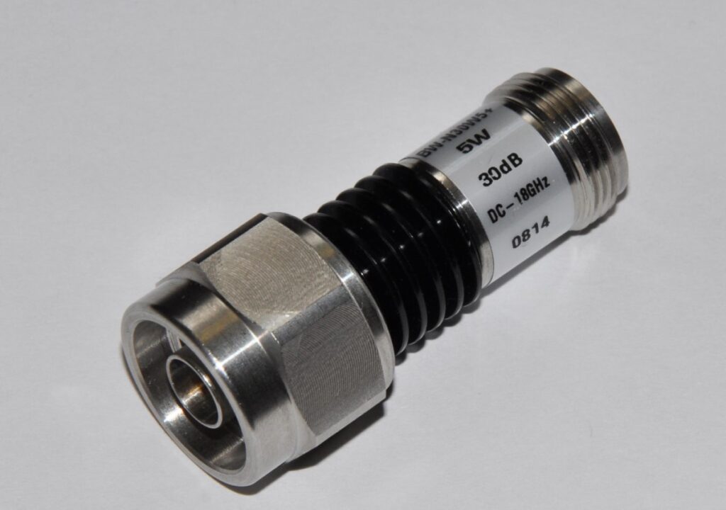
What is a Fixed Attenuator?
The resistor network is locked at a predetermined attenuation setting in fixed-type attenuators. These are installed in the signal path to reduce the signal’s power. According to the application, these can be unidirectional or bidirectional. Surface mount, waveguide, and coaxial options are all available.
The resistance is developed in a chip-based design by the various types of materials put on the thermally conductive substrate. This value is determined by the chip’s size and the materials used in its manufacture.
What is a Variable Attenuator?
In the variable rf attenuator, the attenuation value can be manually modified to any value within the defined range. The resistors in the attenuator network are replaced with solid-state devices such as MOSFETs or PIN diodes in this type.
When compared to a passive resistor network, attenuation in FET devices may be changed with more precision by adjusting the voltage. It is possible to change the attenuation here either manually or through electronic signals.
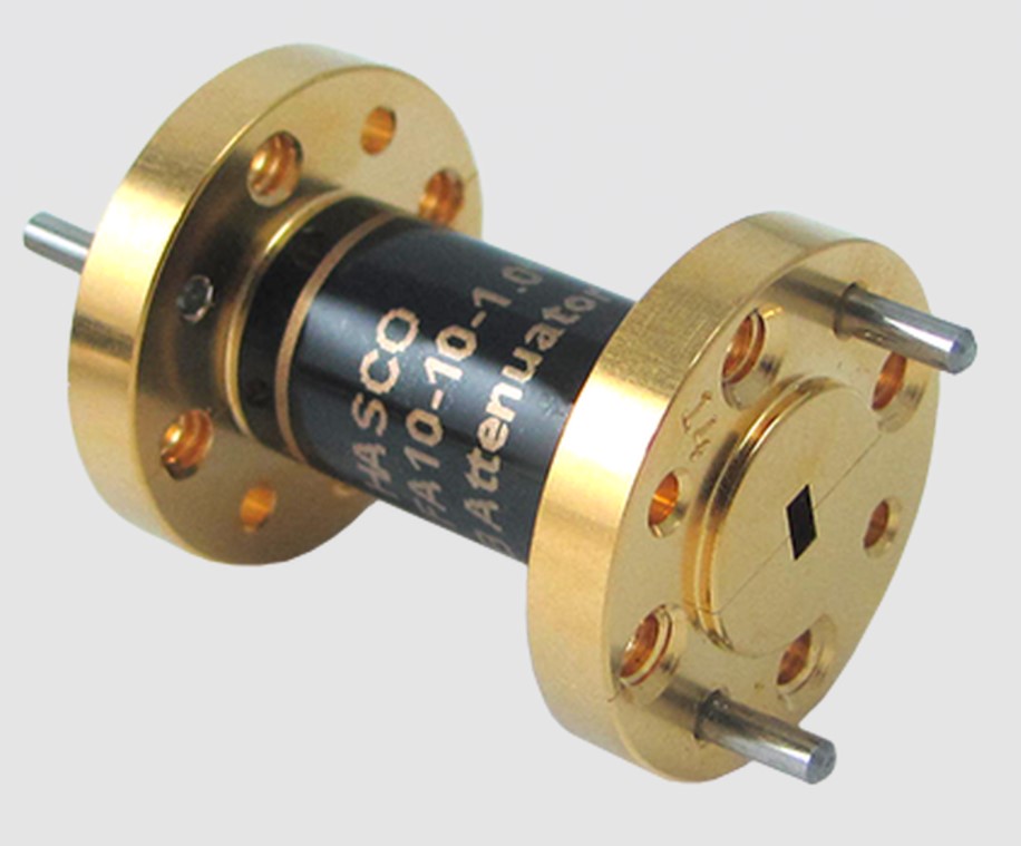
What are Waveguide Attenuators?
By attenuating the input signal, waveguide attenuators may adjust the power level in waveguide systems. The frequency of the waveguide system, the waveguide size, and the desired attenuation level all influence the choice of waveguide attenuators.
Fixed and variable waveguide attenuators are the two most common types of waveguide attenuators. Any signal input to the system will be attenuated by the fixed waveguide attenuators, which have a fixed level of attenuation. A knob, voltage, or programming can change the level of attenuation in variable waveguide attenuators.
Important Factors about Waveguide Attenuators
Waveguide variable attenuators are particularly useful in test-and-measurement systems and in situations where the final required level is unknown or falls within a range. However, choosing a waveguide variable attenuator for a specific application is not easy, and it can be beneficial to understand some of the basic characteristics of these components as well as some essential performance metrics.
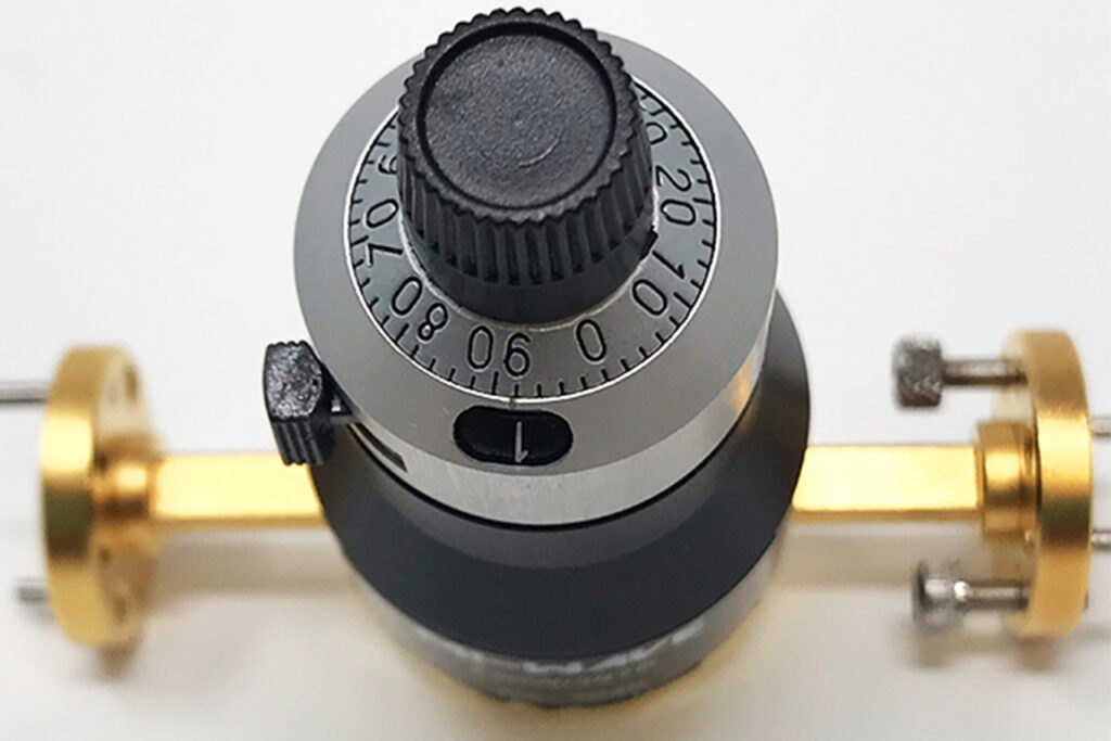
Because there are many various types of waveguide variable attenuators, it’s also useful to understand how the attenuation can be modified. A hand-controlled version or a motor-operated version are two common methods for controlling attenuation.
The attenuator and attenuation value are changed by voltage in the engine-controlled form. Knowing what choices are accessible lets clients choose the best waveguide variable attenuator for their necessities.
Waveguide variable attenuators arrive in an assortment of constriction values, with some equipped for adjusting lessening settings from 0 to 30 dB or more all through waveguide frequency bands with remarkable steadiness and unwavering quality.
Waveguide variable attenuators are accessible with completely electronic control of attenuation, for instance, utilizing PIN diodes to tune the constriction level of the part. Physically tuned waveguide variable attenuators offer the advantages of effortlessness and direct control. Engine or diode-controlled electronically changed waveguide variable attenuators offer the choice of the controller and fast resetting of attenuation level, depending on the situation.
Different techniques can be utilized to show the attenuation level set on one of these parts, from basic mechanical dials to more refined electronic readouts. The decision of attenuation presentation will regularly be controlled by the necessities of a specific application.
Contingent to the requirement for exactness, waveguide variable attenuators are accessible as adjusted or uncalibrated models. Aligned attenuators are commonly confirmed by a provider at various spot frequencies and attenuation settings; albeit these frequencies and attenuation settings can be picked by a client to best match the necessities of an application. The mechanical development of a waveguide variable attenuator might be basic for certain applications.
Waveguide size is an element of the frequency of a recurrence of premium, the actual size of most waveguide variable attenuators (like the length) will be for the most part controlled by the working frequency, with frequency attenuators being significantly bigger than higher-recurrence attenuators, despite the fact that they may normally be appraised for similar power-taking care of capacities. The sort of flanges utilized on the waveguide info and result ports might be of importance for the drive system’s design.
Conclusion
To prevent potentially catastrophic reflections back to the source, attenuators are built with minimal reflections and a low Voltage Standing Wave Ratio (VSWR). With the above-mentioned factors about waveguide attenuators, we hope you are clear with why you need to use a waveguide attenuator.


